Blog 3: Design for 3D Printing
- harrenchd
- Jul 12, 2024
- 2 min read

Updated: Aug 7, 2024
Welcome back! Thanks for stopping by again. It's been a while since the last blog was written, so let me cover what I've done so far!

I've learnt to use an online software called Fusion 360, which allows us to create sketches
and models, and eventually 3D print them to make them come to life. Pretty cool, huh?
Before I go on about my project and how I managed to survive doing it, let's talk more about 3D printers! The more commonly used types of 3D printers are the Fused Deposition Modeling (or FDM for short) and the Stereolithography (SLA) printers because they are more affordable options, and thus are used mostly amongst hobbyists and makers. The printers used in our school are the FDM printers. They work by melting plastic filaments from an extruding nozzle, which is then deposited in layers onto the print bed of the 3D printer until the print model is created.
The Not So Cool Part:

Unfortunately, making a 3D-printed object means we have to create a design on Fusion first.
Though I admit the process was somewhat fun, this project was not it. For starters, we were assigned a case each to work on, and design an object that meets the objective. As for me, I was tasked with Case 3: to design a vertical arm that can contain a motor connected to a gantry pole, which is used for toy cars. A sketch was made to give us a rough idea on what our final product should have looked like:

There wasn't much room for creativity for this particular project, so I just went straight to designing the gantry using this sketch as reference. I decided to split the main body into 3 parts: The stand, the compartment housing the motor and the cover of the compartment. This allowed me to portion my work easily and focus on particular parts of the project that I wanted to work on, which was greatly beneficial as I was somewhat rushing for time towards the end of the report.
Planning my Designs:
Before getting into actually creating my sketches, I had to sketch what I actually wanted to make to avoid any mistakes (which I did not) and plan out the dimensions and shapes of my model.
Dimensions of the compartment:

I had to estimate the dimensions of the compartment just from the dimensions of the servo motor that I had measured, which was quite difficult to do, because I forgot to measure some parts of the motor such as the wires, and a small part of the motor that extruded out of the sides. Also, the box had to be perfectly sized to both fit the motor and prevent unnecessary use of materials.
The height of the gantry:

This was another big question mark. Since the height of the toy car was not specified, I
went to do some research to find out that the average Hot Wheels car was about 1 inch (~2.54 cm), and I rounded it up to 3 cm to account for some cars that could be taller. This height is for the base height of the stand, and does not include the height of the compartment.
How the cover should fit on the compartment:

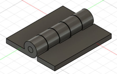
This one was the easiest to decide from the other considerations, but it was definitely the hardest to actually do. I went with making hinges that connected to the sides of the cover as it would make it easier to make the cover since it could just be the same length and width of the compartment. I was wrong. Making the hinge made me look at other resources and spend as much time as making all the other components COMBINED. This caused me physical pain. But it brought about a very important lesson: Never to use hinges unless necessary.
Now we can create the sketch!


Comments